

Size an HFO power plant from the highest critical net load that must remain supplied after the largest generating unit is unavailable. Start with an interval load profile, convert each candidate engine from reference gross output to site-rated net output, and then test the unit combination under normal, low-load, and one-unit-out conditions.
N+1 is not a percentage added to peak demand. It is a configuration test. A plant can have more installed megawatts than the site’s peak and still fail N+1 because ambient derating, auxiliaries, or the loss of one large unit removes too much usable capacity.
What load data should determine plant size?
For an operating site, use at least 12 months of 15-minute or hourly meter data. Monthly bills do not show peak duration, simultaneous starts, or demand changes between shifts.
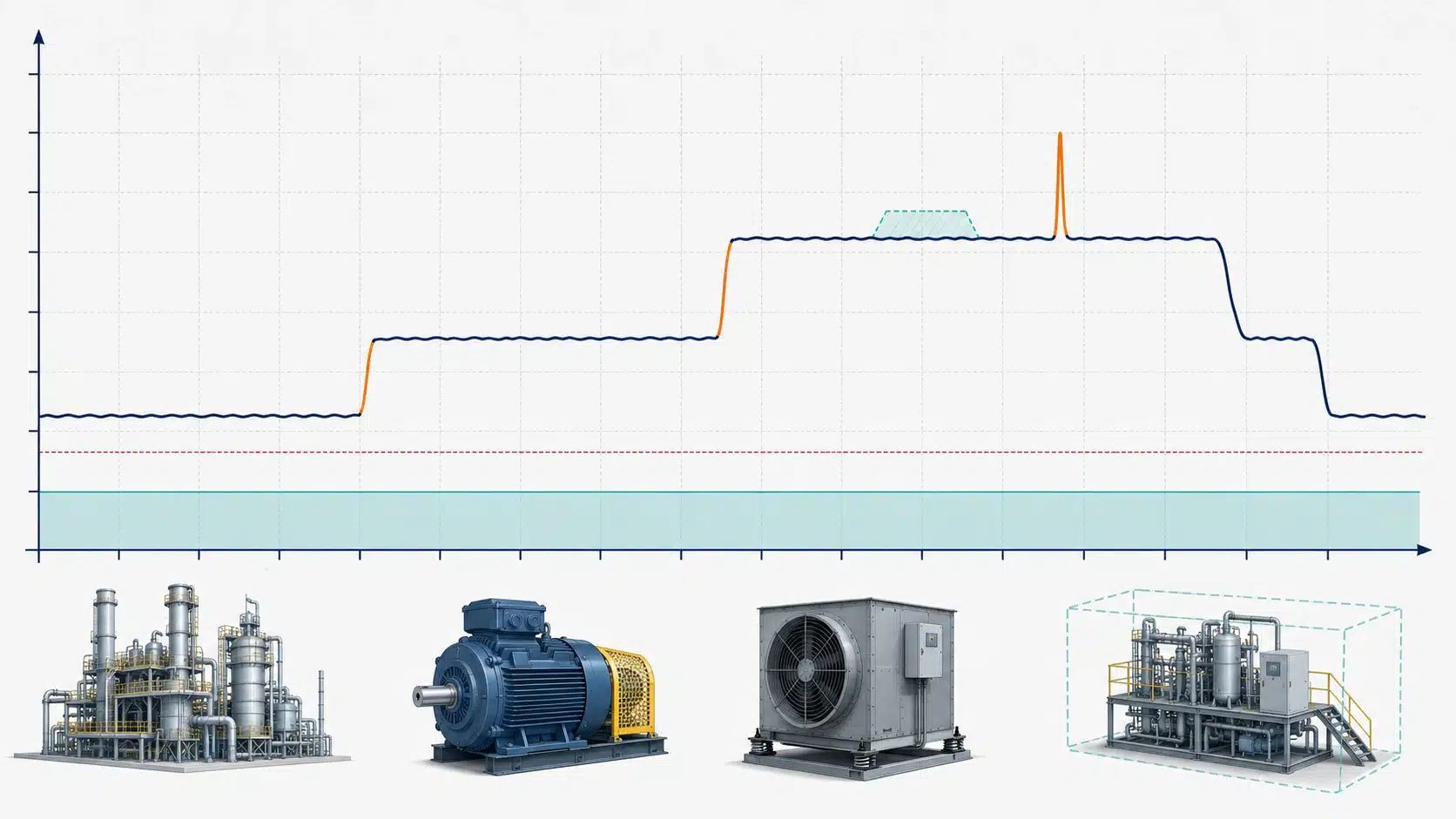
For a new site, build the profile from operating modes rather than adding every equipment nameplate. Separate:
- Continuous process loads that establish the base demand
- Intermittent loads and their simultaneity
- Large motors, transformers, and other step-load events
- Critical loads that must survive a generating-unit trip
- Loads that can be shed, delayed, or transferred
- Approved expansion loads with a defined commissioning date
Motor starting also needs a transient check. A short starting event may govern alternator kVA, voltage dip, and engine load acceptance without setting the continuous MW requirement. Submit the load sequence—not only a total connected-load spreadsheet—before selecting engines.
How do you convert gross rating into net output?
A catalogue rating is not the power available at the customer busbar. Site conditions and duty rating can reduce output before auxiliaries take their share.
Screen each candidate unit as follows:
Site-rated gross output = reference gross output × site-output factor
Site-rated net output = site-rated gross output − operating auxiliary demand − delivery losses
The site-output factor must come from the supplier’s correction method for the specified ambient and fuel conditions. Do not reuse a generic altitude or temperature percentage from another engine model.
A complete HFO power plant configuration should state gross and net output at a defined delivery point. Auxiliaries include fuel heating and treatment, pumps, cooling, compressed air, water treatment, emissions equipment, and controls. Some loads change with engine count or ambient temperature, so one percentage may suit screening but not final design.
Freeze the ambient case, duty rating, and electrical boundary before comparing unit capacities.
How should unit size and quantity follow the load profile?
The best combination keeps running engines inside their approved range across most of the load-duration curve. One oversized engine may cover the peak yet operate inefficiently at low load and force a total outage during maintenance.
Smaller parallel units let operators stop one unit and load the remaining engines more strongly as demand falls. The tradeoff is more switchgear, controls, auxiliaries, and maintenance events.
Larger units reduce equipment count but make each outage more severe. Losing one 8 MW machine is a different reliability event from losing one 4 MW machine, even when both plants have the same total installed capacity.
Use the selected engine’s guaranteed fuel-consumption curve, permitted continuous operating range, and maintenance schedule. There is no universal minimum-load percentage that should be applied to every HFO engine. Choose the smallest practical number of units that satisfies dispatch, maintenance, and firm-capacity requirements.
What does N+1 mean for an HFO plant?
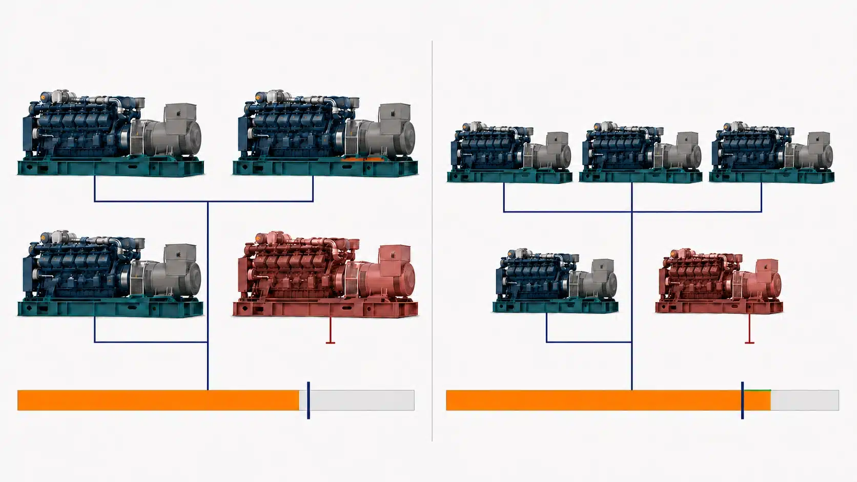
N+1 means the remaining available units can supply the defined critical load after one generating unit is unavailable. For identical units, a simplified screening formula is:
N+1 firm net capacity = (installed unit count − 1) × site-rated net output per unit
Compare that result with critical peak demand, not automatically with every nonessential load. If the design relies on load shedding after a trip, identify the exact feeders, sequence, and allowable interruption time in the operating philosophy.
Review power system configurations because generator N+1 does not protect a plant with one fuel separator, one booster pump, one auxiliary transformer, or one common bus that can stop every engine. Define redundancy for fuel treatment, cooling, starting air, controls, transformers, and switchgear according to the consequence of failure.
Accept the N+1 claim only after the single-line diagram and balance-of-plant responsibility matrix show what remains operational during each credible outage.
What does a 15 MW-plus sizing example look like?
Consider a hypothetical site with an 18.0 MW normal peak, a 16.5 MW critical peak, a 12.0 MW average load, and a 7.0 MW minimum load. Assume a 0.95 site-output factor and auxiliaries equal to 6% of site-rated gross output. These are calculation inputs, not equipment guarantees.
Compare installed and firm capacity
| Screening item | Four × 6 MW units | Five × 5 MW units |
| Installed gross capacity | 24.0 MW | 25.0 MW |
| Site-rated net output per unit | 5.358 MW | 4.465 MW |
| All-units net capacity | 21.432 MW | 22.325 MW |
| N+1 firm net capacity | 16.074 MW | 17.860 MW |
| Critical-load N+1 result | Short by 0.426 MW | Passes by 1.360 MW |
| Dispatch at 12 MW average | Three units at about 74.7% each | Three units at about 89.6% each |
The four-unit option has 24 MW installed—well above the 18 MW normal peak—but still fails the critical-load N+1 test. The five-unit option passes because losing one smaller machine leaves 17.86 MW net.
Check minimum-load dispatch
At the 7 MW minimum, two 5 MW units would each carry about 78.4% of their simplified net rating. The dispatcher can stop unnecessary units instead of spreading the load thinly across the entire plant. Validate both options with supplier curves and a dynamic study before selecting the five-unit arrangement.
Which operating cases must the design pass?
Test the operating events—not only the peak MW balance. Include:
- Minimum stable site demand with the fewest practical units online
- Average and maximum normal demand across seasonal ambient conditions
- Loss of the largest online unit, including frequency and voltage response
- One unit under planned maintenance during a high-demand period
- Start of the largest motor or the most severe scheduled load block
- Failure or maintenance of a shared fuel, cooling, or electrical auxiliary
- Approved future load after the planned expansion date
A steady-state balance cannot prove the plant will survive an engine trip or motor start. A transient study must check governor response, alternator excitation, voltage dip, frequency deviation, spinning reserve, and staged load shedding. Put automatic start, synchronization, and recovery times into the control specification.
Reject any configuration that passes only the annual energy balance while failing a credible operating event.
What should suppliers guarantee before selection?
Every bidder should calculate against the same load file, ambient conditions, fuel specification, and delivery boundary. Request a common schedule covering:
- Reference and site-rated gross output for every engine-generator
- Net plant output with auxiliaries itemized by operating mode
- Guaranteed fuel consumption at the required load points and stated tolerance
- Approved continuous-load range and overload capability
- Maximum accepted load step, voltage dip, and frequency response
- N+1 firm capacity with the largest unit unavailable
- Unit commitment logic for minimum, average, and peak demand
- Planned maintenance hours, overhaul intervals, and onsite spare strategy
- Redundancy and isolation philosophy for each balance-of-plant system
- Expansion interfaces, switchgear limits, and commissioning tests
Tie those guarantees to the EPC project development scope so the engine supplier, fuel-system contractor, and electrical integrator do not calculate different net capacities. Compare offers only after every bidder returns the same operating-case table.
Size firm capacity, not the brochure total
The correct plant size is the net capacity that remains usable during the project’s worst credible operating condition. Installed gross MW is only a starting point.
A design with slightly more nameplate capacity can be the better choice when smaller modules improve one-unit-out capacity, maintenance access, and normal dispatch. Freeze the critical-load definition, site-rating conditions, auxiliary schedule, and single-failure boundary before commercial negotiation. Otherwise, the project may purchase enough engines on paper and still lack enough electricity when one unit stops.