

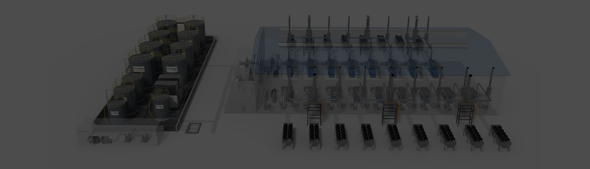
HFO Power Plant Solutions
Integrated power generation for industrial, off-grid and multi-megawatt projects.
What Is an HFO Power Plant?
An HFO power plant generates electricity by using heavy fuel oil in medium-speed engine generator sets. Because HFO must be heated and conditioned before it reaches the engine, the plant requires more than a generator set alone. Fuel storage, transfer, separation, filtration, temperature and viscosity control, electrical systems, cooling and plant controls must work as one system.
In a typical Powermax Energy configuration, HFO is the main operating fuel and diesel serves as the auxiliary fuel. Diesel is commonly used during start-up, shutdown and fuel-system flushing. The fuel supply module manages the changeover between the two fuels according to the selected operating procedure.
When Does an HFO Power Plant Make Sense?
An HFO power plant is generally considered where a project has substantial power demand, long operating hours and dependable access to suitable heavy fuel oil. It may provide an alternative to grid extension, diesel-only generation or other thermal power options, depending on local fuel and infrastructure conditions.
How Does an HFO Power Plant Work?
HFO is transferred from bulk storage to heated settling or buffer tanks and then sent through the fuel-treatment system. Separation and filtration remove water and solid contaminants. The conditioned fuel is heated to the required operating state before the fuel supply module delivers it to the engine.
The engine converts the fuel’s chemical energy into mechanical power, and the alternator converts that power into electricity. Depending on the project, the generating units can supply an isolated site, operate in parallel with other units or synchronize with a utility grid. The plant control system coordinates generator operation, protection and electrical distribution.
Diesel provides a separate support route for start-up, shutdown, flushing and, when the selected configuration permits, diesel operation. Exhaust-gas and engine-cooling heat can also be evaluated for heat recovery. Emissions-control equipment is engineered according to the applicable fuel, operating profile and local limits.
Process flow:
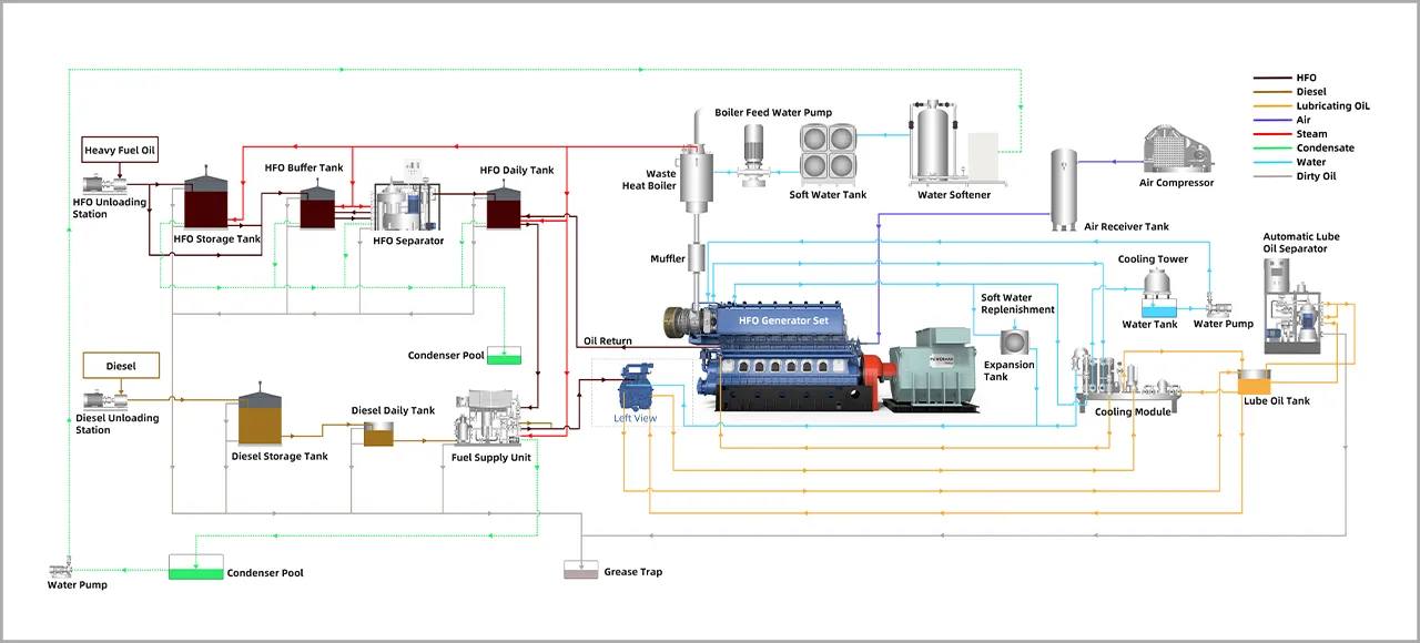
Complete HFO Power Plant System
Powermax Energy defines the plant around the engine, fuel and site interfaces. The final supply scope is agreed during project engineering and may range from core generation equipment to a broader integrated plant package.
Fuel Storage and Transfer
Bulk storage tanks, buffer or settling tanks, day tanks, transfer pumps, heating and associated piping maintain an organized fuel route from delivery to consumption. Tank capacities and redundancy are selected from the site’s delivery schedule and required operating autonomy.
HFO Treatment and Supply
The HFO separator skid and fuel supply skid combine the main conditioning functions needed before combustion, including heating, oil-water separation and filtration. The detailed equipment selection depends on the submitted fuel analysis and engine requirements.
HFO Generator Sets
Powermax Energy 300 Series medium-speed generator sets form the core of the plant. Unit size and quantity are selected to match the load profile, required reserve margin, maintenance strategy and future expansion plan.
Cooling, Lubrication and Plant Auxiliaries
Cooling circuits, lubrication equipment, starting systems, ventilation and other auxiliaries are coordinated with the engine and local ambient conditions. Their electrical demand should be included when calculating the plant’s net output.
Electrical Integration and Plant Control
Alternators, switchgear, protection, synchronization and control systems connect the generating units to the plant distribution network or utility interface. The operating philosophy is configured for single-unit, multi-unit, island-mode or grid-parallel operation as required.
Heat Recovery and Emissions Options
Exhaust-gas and jacket-water heat recovery can be evaluated where a site has a useful thermal load. Project-specific emissions options may also be integrated to address applicable NOx, SOx and particulate limits. These systems are selected after the fuel properties and local requirements are confirmed.
Powermax Energy HFO Generator Set Range
The Powermax Energy 300 Series is designed for prime-power applications and can be used as a single generating unit or combined into a multi-unit HFO power plant.
| Parameter | Available configuration |
|---|---|
| Rated output | 1,000–4,000 kWe prime power per unit |
| Engine platform | Powermax Energy 300 Series medium-speed engine |
| Frequency | 50 Hz or 60 Hz |
| Fuel arrangement | HFO as main fuel; diesel as auxiliary fuel |
| Electrical output | Low- or medium-voltage options, subject to model and project design |
| Plant arrangement | Single-unit or multi-unit parallel configuration |
*Final ratings, fuel limits and electrical parameters are confirmed against the project conditions and selected model.
HFO Power Plant Applications
Remote Mining and Mineral Processing
Mines and processing facilities often require substantial power where grid capacity is limited or unavailable. A multi-unit layout can follow changing production loads while allowing planned maintenance on individual units.
Industrial Manufacturing and Captive Power
Factories with sustained electrical demand can use an HFO plant as a dedicated power source or as part of a broader captive-energy strategy. Where process heat is required, heat-recovery options can be evaluated at the same time.
Islands and Remote Grids
For isolated grids, the plant must balance generation capacity, reserve margin and daily load variation. Multiple units can provide greater operating flexibility than one large generating block.
Oil, Gas, Port and Fuel-Terminal Facilities
Sites with established liquid-fuel handling infrastructure may be well positioned to manage HFO delivery, storage and treatment. The plant design must still reflect the actual fuel specification, site safety requirements and electrical demand.
IPP, Utility and Regional Power Projects
Independent power producers and utilities can configure several generator sets into a modular power plant. Capacity can be divided across units to support dispatch planning, maintenance and phased project development.
Combined Heat and Power
When a facility has a simultaneous demand for electricity and usable heat, exhaust-gas and engine-cooling energy may be recovered for steam, hot water or other thermal processes. The opportunity should be assessed against the site’s real heat profile.
From Project Assessment to Plant Operation
An HFO project begins with the operating conditions—not a fixed equipment list. Powermax Energy works with owners, EPC contractors and project developers to define the generating system and its interfaces.

Project
Assessment
Read More

Project Assessment
We review the load profile, operating hours, site conditions, electrical system, fuel logistics and development objectives. This establishes the design basis and identifies information still required.

Fuel and System Engineering
Read More

Fuel and System Engineering
A representative fuel analysis is used to develop the fuel-treatment concept. Unit selection, plant capacity, redundancy, auxiliary systems and integration boundaries are then defined for the project.

Manufacturing and Integration
Read More

Manufacturing and Integration
Generator sets and agreed auxiliary modules are manufactured and prepared for system integration. Inspection and factory testing requirements are established in the project documentation.

Delivery and Commissioning Support
Read More

Delivery and Commissioning Support
The delivery scope may include equipment supply, installation guidance, commissioning support and operator training. Responsibilities and site interfaces are clarified before execution.

Lifecycle
Support
Read More

Lifecycle Support
Recommended spare parts, maintenance planning and technical support are aligned with the plant’s operating profile and location. The final service arrangement is agreed for each project.