
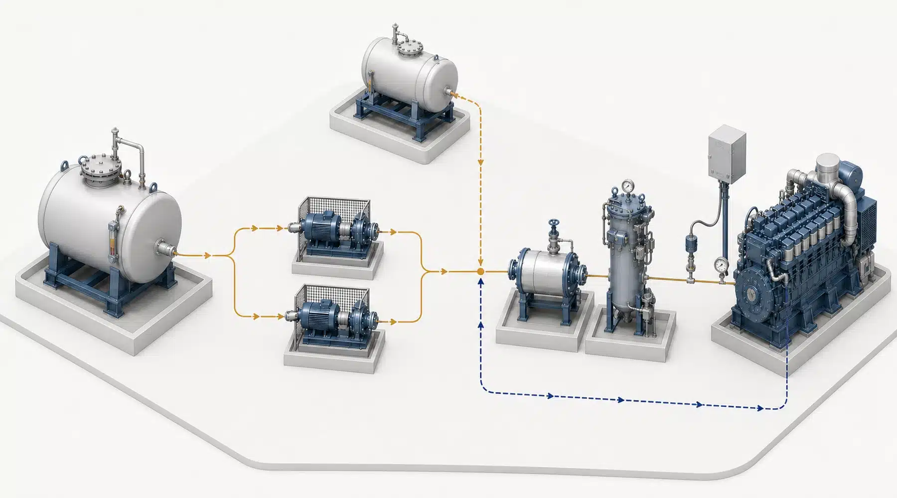
An HFO fuel treatment system turns heated but contaminated residual fuel into a clean, pumpable, correctly conditioned fuel that a medium-speed engine can inject. The route normally runs from heated storage through settling, preheating, centrifugal separation, and a service tank, then through a pressurized supply loop with final filtration and viscosity control.
The separator does not do the whole job. A clean separator outlet can still become an engine problem if incompatible fuels form sludge in the tank, the service tank collects water, or the booster unit delivers the wrong viscosity. Treat the installation as one fuel-quality chain from delivery sample to engine inlet.
What Must the System Remove or Control?
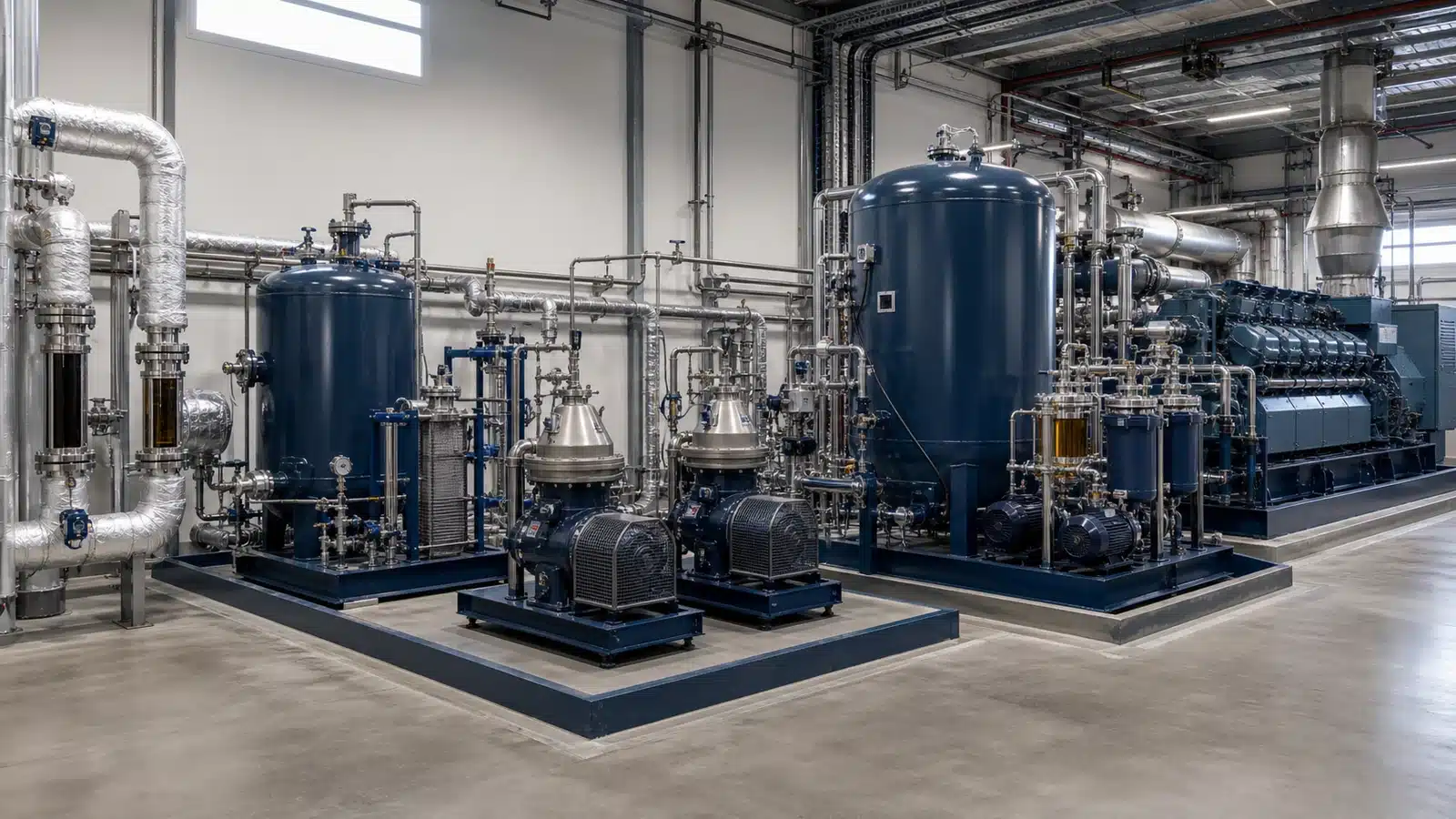
Four conditions matter at the engine inlet: abrasive solids, water, viscosity, and fuel stability. Rust and sand may enter during transport or storage, while catalytic fines can remain from refinery processing. Water promotes corrosion and poor combustion; excessive viscosity prevents proper atomization.
Fuel stability creates a different risk. Two fuels can each meet a purchase specification yet form heavy sludge when mixed. That sludge loads the separator, blocks filters, and can starve the engine. Keep new deliveries segregated until laboratory results and a compatibility check support mixing.
The treatment design therefore begins with a representative fuel analysis and the selected engine manufacturer’s current inlet limits.
Powermax Energy applies the same fuel-first logic to an HFO power plant solution: storage, treatment, supply, and generation must be engineered as connected systems. Approve the process basis before comparing separator models.
How Does HFO Move from Storage to the Engine?
The complete route has seven functional stages, and each stage prepares the fuel for the next one. Exact tank temperatures, separator feed rates, filter grades, and engine-inlet viscosity remain fuel- and engine-specific.
The treatment train
Stage Main equipment What happens What operators must verify 1. Receive and store Unloading station, heated storage tanks, transfer pumps The plant samples the delivery, keeps the fuel pumpable, and avoids uncontrolled mixing between batches. Fuel identity, laboratory sample, tank level, heating availability, and segregation 2. Settle Heated settling or buffer tank with sloped bottom and drains Lower viscosity and residence time allow free water and coarse sediment to fall toward the drain. Temperature, drain condition, water/sludge removal, and usable residence time 3. Pre-strain and pump Suction strainer and separator feed pump Coarse debris is stopped before it damages the pump or enters the separator. Differential pressure, pump flow, and standby readiness 4. Heat for separation Controlled preheater Heating reduces viscosity so water and dense particles can move through the oil and separate more effectively. Temperature at the separator inlet, stable flow, and heater control response 5. Centrifuge Self-cleaning disc-stack separator Centrifugal force sends water and dense solids outward while cleaned oil leaves through a separate path; periodic discharge sends contamination to the sludge system. Feed rate, clean-oil water indication, discharge cycle, and sludge route 6. Hold clean fuel Heated service or day tank The tank provides a ready inventory between the treatment skid and engine supply loop. Tank drains, temperature, turnover, overflow route, and low-level reserve 7. Condition and supply Booster and circulating pumps, final heater, viscosity controller, automatic filter, and venting device The loop maintains pressure, removes remaining particles, and sets injection viscosity before fuel reaches the engine. Engine-inlet pressure, viscosity, filter differential pressure, and return temperature
Purifier or clarifier
In purifier operation, water and solids leave through different paths; a clarifier is configured primarily for solids. Some plants use a single modern separation stage, while others use two stages or flexible parallel/series operation. Select the arrangement from the delivered fuel, required cleanliness, and OEM guidance, not from a generic flow diagram.
Why Do Heating and Separator Flow Work Together?
Heating makes HFO pumpable and improves separation, but one temperature cannot serve every point in the system. Storage heating prevents the fuel from approaching its pour point. Settling-tank heating lowers viscosity without encouraging asphaltene precipitation. The separator preheater then brings the oil to the viscosity required for effective centrifuging.
Separator residence time
Higher throughput is not automatically better. Fuel that crosses the separator bowl too quickly has less residence time, so smaller water droplets and particles are more likely to leave with the clean oil. Size the separator above consumption demand, then operate it at the feed rate and temperature that achieve the required outlet quality.
OEM inlet targets
Engine supply has another setpoint. One MAN four-stroke guideline, for example, specifies 12–18 cSt injection viscosity for named genset families and gives post-separation examples below 15 mg/kg Al+Si and below 0.2% water by volume. Those figures illustrate how an OEM connects treatment performance to engine protection; they are not universal limits for another engine.
Use the selected engine manual, separator performance data, and viscosity-temperature curve as one design package. A heater sized without the separator, or a separator sized without the actual fuel density and viscosity, leaves an unresolved interface.
What Protects the Engine after Centrifugal Separation?
The final filter is the last barrier against particles carried through the centrifuge or released from downstream piping. An automatic backflushing filter supports continuous operation, while a duplex or bypass arrangement allows maintenance without sending unfiltered fuel to the engine. Its filtration grade and allowable differential pressure must match the engine specification.
Pressure and viscosity control
The booster module keeps the supply loop pressurized and circulates more fuel than the engine consumes. The final heater and viscosity controller adjust temperature as fuel properties and engine load change. Pressure, temperature, and viscosity must be measured near the engine inlet; a perfect reading at the service tank does not prove correct injection conditions.
Diesel changeover
Many HFO plants also retain a diesel route for start-up, shutdown, and flushing. Changeover must control temperature and viscosity gradients so pumps and injection equipment do not receive an abrupt fuel-property change. Test the entire changeover sequence during commissioning, including valve feedback and return-line routing.
How Do You Know the Treatment System Is Working?
Samples taken before and after the separator reveal more than a green “running” indication on the control panel. Compare water and abrasive contamination at both points, trend filter differential pressure, and record separator feed temperature, flow, and sludge-discharge frequency. A deteriorating trend catches fuel changes and equipment problems before injectors become the test instrument.
Redundancy
For continuous-duty plants, specify maintainable redundancy. Two full-capacity separators, or another documented arrangement that preserves clean-fuel supply during maintenance, is stronger than one large machine with no service window. Pumps, heaters, filters, and control power also need a clear standby philosophy; separator redundancy alone does not remove a single point of failure.
Acceptance evidence
Acceptance documents should answer these questions:
- Which laboratory fuel properties define the design case and worst credible case?
- What clean-fuel limits apply at the separator outlet and engine inlet?
- At what fuel temperature, viscosity, and feed rate is separator performance guaranteed?
- Can operators isolate and maintain one train while the plant remains online?
- Where are the sample points, drains, sludge tanks, alarms, and automatic shutdowns?
- Which consumables and tools belong on the critical spare-parts list?
- Does the plant O&M plan turn alarms, samples, and trends into defined operator actions?
Include these checks in factory and site acceptance tests. If the operator cannot sample the clean fuel, confirm the active duty/standby train and see the engine-inlet viscosity during a shift, the control plan is incomplete.
Start with the Fuel, Not the Separator
Specify the engine-inlet result before specifying the skid. The next fuel delivery may carry more water, a different density, or an incompatible blend, so a treatment system must have enough control range, residence time, and maintainable redundancy to handle variation without sacrificing cleanliness.
The strongest procurement package ties a representative fuel analysis to OEM limits, guarantees performance at stated operating conditions, and proves it with accessible sample points. That changes acceptance from “the separator runs” to “the engine receives verified fuel.” It is the distinction that protects both uptime and the maintenance budget.